IHC Floor plan

This project explores the use of a physical floor plan of Indian Heritage Center(IHC) to support curators and the production team in planning future exhibitions. It includes miniature scaled models of key exhibition elements such as plinths, paintings, and figures to visualise spatial arrangements effectively and optimise exhibition planning before production commences.

Introduction

Purpose of Project

Building on the experience from The Peranakan Museum project, this phase explores new design considerations by developing a modular floor plan for the IHC, which features a more unconventional layout. The goal is to test solutions that meet curatorial needs while remaining space-efficient. This project will progress alongside the design and production of the Sun Yat Sen Nanyang Memorial Hall(SYS) floor plan.

Current Approach

Planning IHC exhibitions with 2D floor plans presents limitations similar to those seen in the TPM project. Without depth or volume, curators find it challenging to visualise artwork placement, leading to uncertainty around scale and spatial relationships. Key factors such as sight lines, spacing, and visitor flow are often misjudged, and the absence of a shared 3D reference can hinder coordination with production teams.

Proposed Solution

Following the approach used for TPM, this method involves producing a 3D-printable physical floor plan in-house, allowing for easy updates to layout or structural elements without relying on external suppliers. To help curators visualise spatial arrangements, the model includes miniature features such as plinths and platforms, improving clarity on object placement and scale while enhancing communication with production teams.

PRoject Details

Project Requirements

The IHC museum floor plan will incorporate a magnetic base plate to hold modular, interchangeable components. Miniature elements such as figures, plinths, and partitions will be colour-coded for clarity and fitted with magnets for easy repositioning. Walls will stand at 6CM, representing a real-world height of 3 metres. Due to IHC’s irregular layout, a uniquely shaped section of the floor plan will be designed to detach and reattach magnetically for greater flexibility.

Project Deliverables

1. A physical floor plan of the exhibition areas on Levels 3

2. Each set contains a variety of miniature components, including human figures, plinths, and modular walls, available in four colour schemes for testing different visual combinations.

Team Members

Bao Songyu

Muhammad Syahid Mustapa

Noor Aliff

Tanya Singh

Project Budget

S$5950 (shared with the development of SYS Floor Plan)

Design Considerations

Odd Shaped Layout

A main challenge in this project was creating a floor plan model for IHC’s irregular exhibition layout, which includes a protruding section beyond the main hall. To address space and storage limitations, the solution involves designing part of the model as a removable segment, allowing it to remain compact while still accurately representing the full layout.

Track lights Representation

An acrylic overlay will be placed above the floor plan to indicate the positioning of track lights on the ceiling. This transparent guide allows curators to plan lighting arrangements more efficiently, reducing the need for repeated on-site visits. It supports smoother exhibition curation by providing a clear visual reference for how lighting interacts with the layout and display areas.

Materials and Parts

The floor plan will be mounted on a wooden base for structural stability, with the 3D printed PLA model fixed on top. As both the base and floor plan are magnetic, any major adjustments such as changes in false wall thickness can be made by reprinting the entire model. This approach avoids excessive loose components and simplifies updates without modelling each element separately.

Version Control

IHC FloorPlan Ver Control Tab 1

01

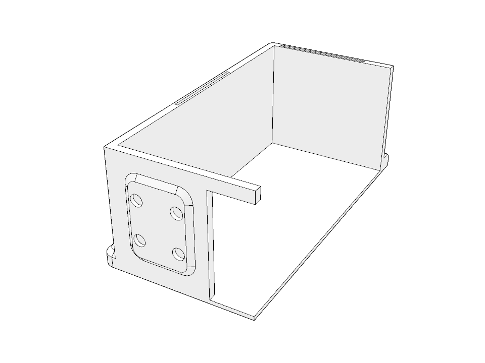
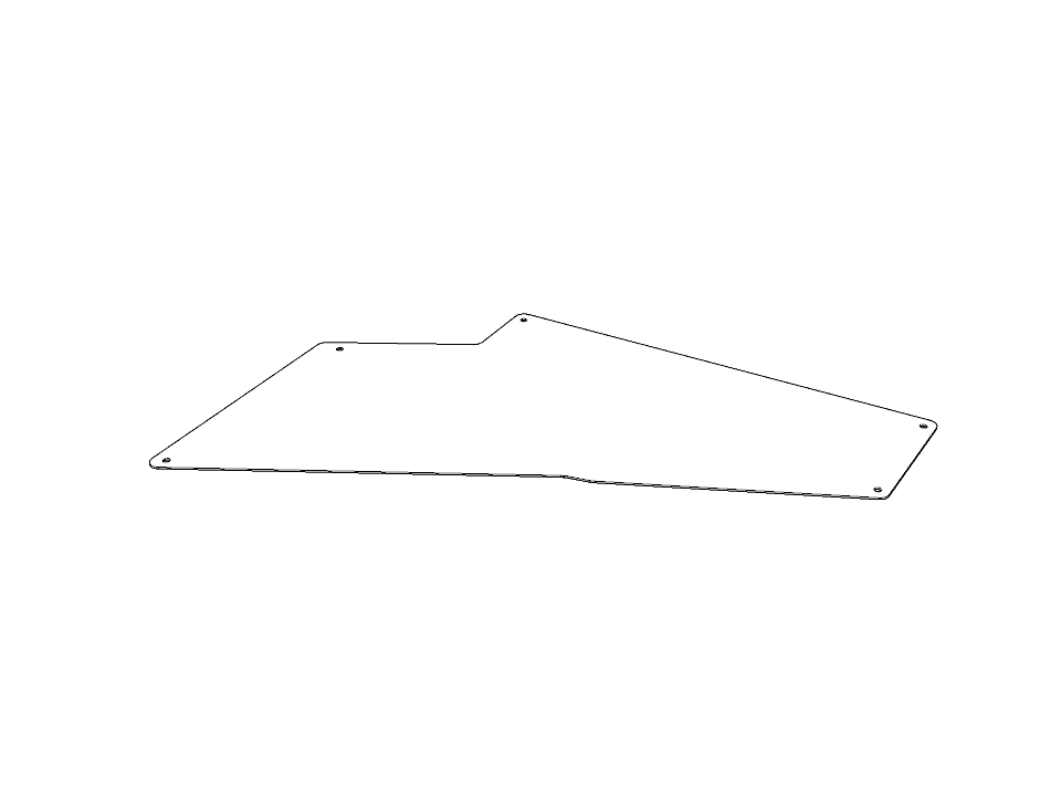
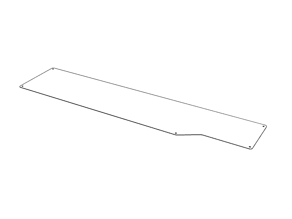
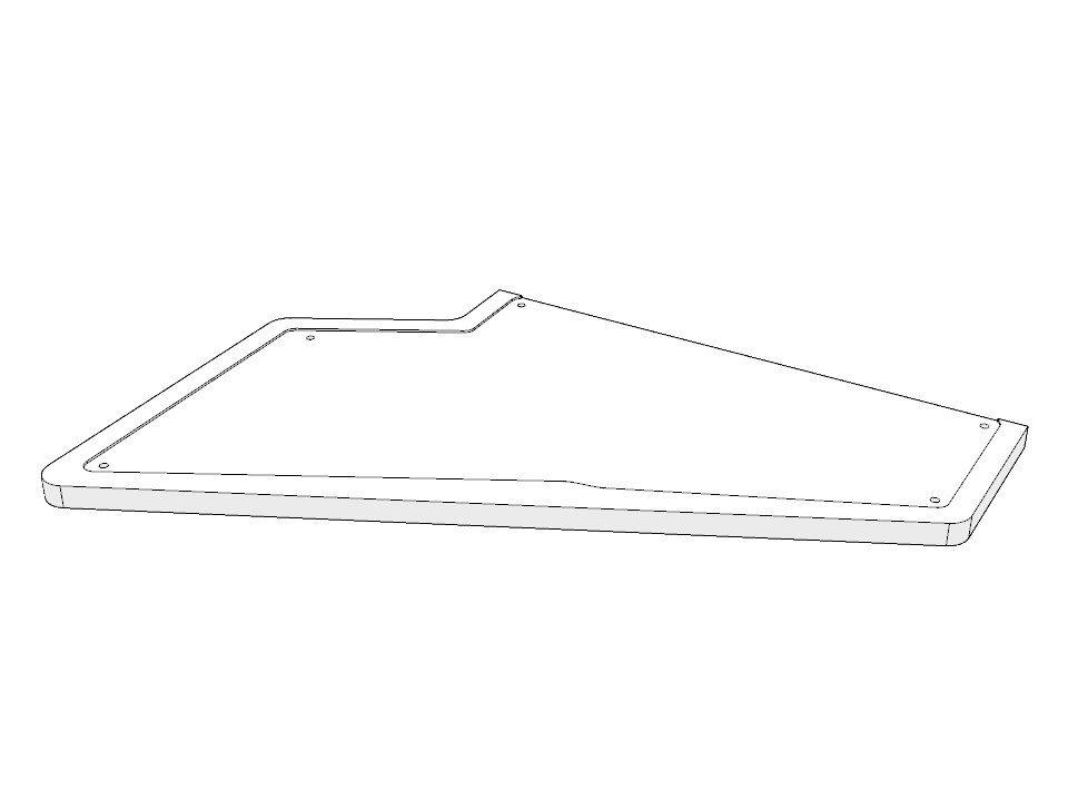
Detachable Acrylic Panel

The CNC-machined acrylic panel fits securely onto the detachable floor plan section, ensuring precise alignment and functional use for exhibition planning.
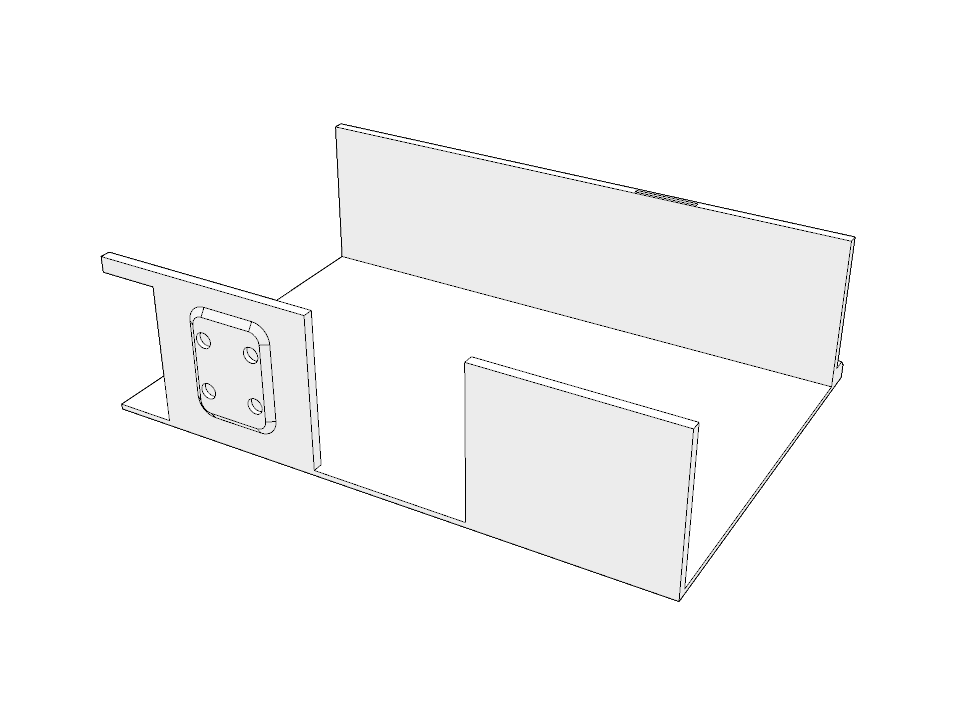
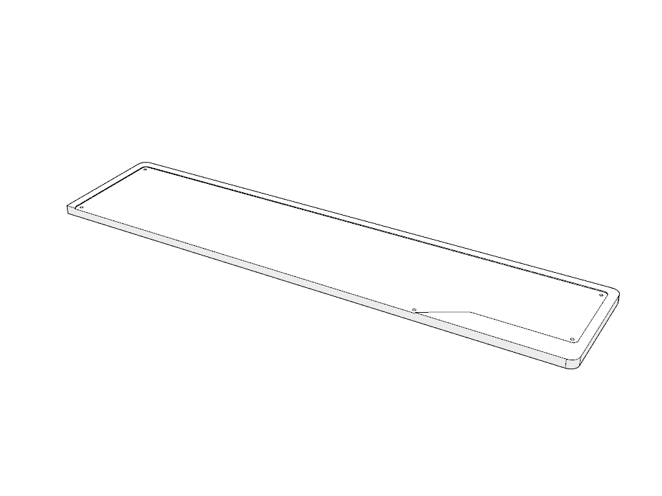
02

Main Acrylic Panel

This acrylic panel features the gallery’s lighting plan etched onto its surface. Its purpose is to help users visualise the placement of lighting within the gallery space, making it easier to plan and curate the exhibition effectively.
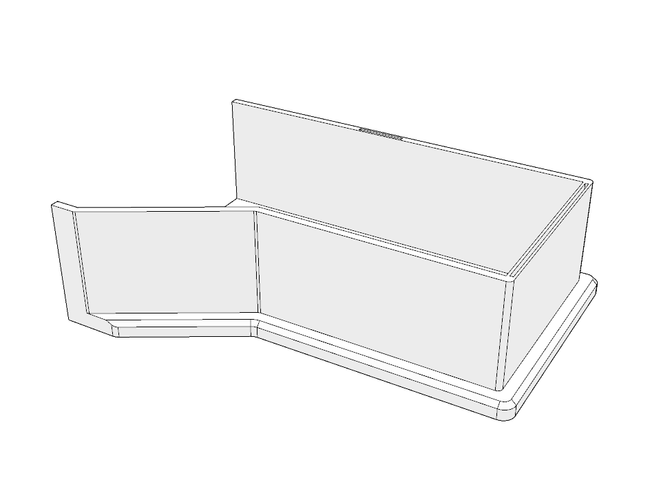
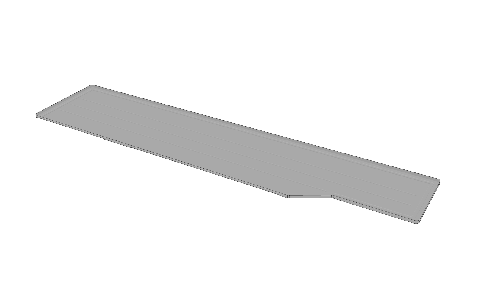
03

Main Wooden Panel

This wooden panel serves as the base of the entire floor plan structure. It provides foundational support, securing both the steel panel and the 3D-printed floor plan in place. Side handles are integrated into the panel design to facilitate easy transport.

04

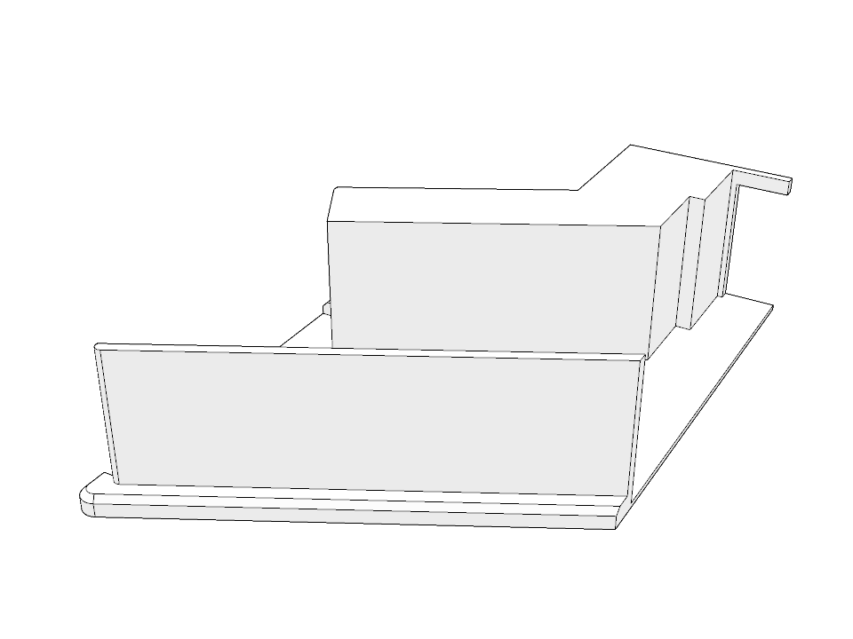
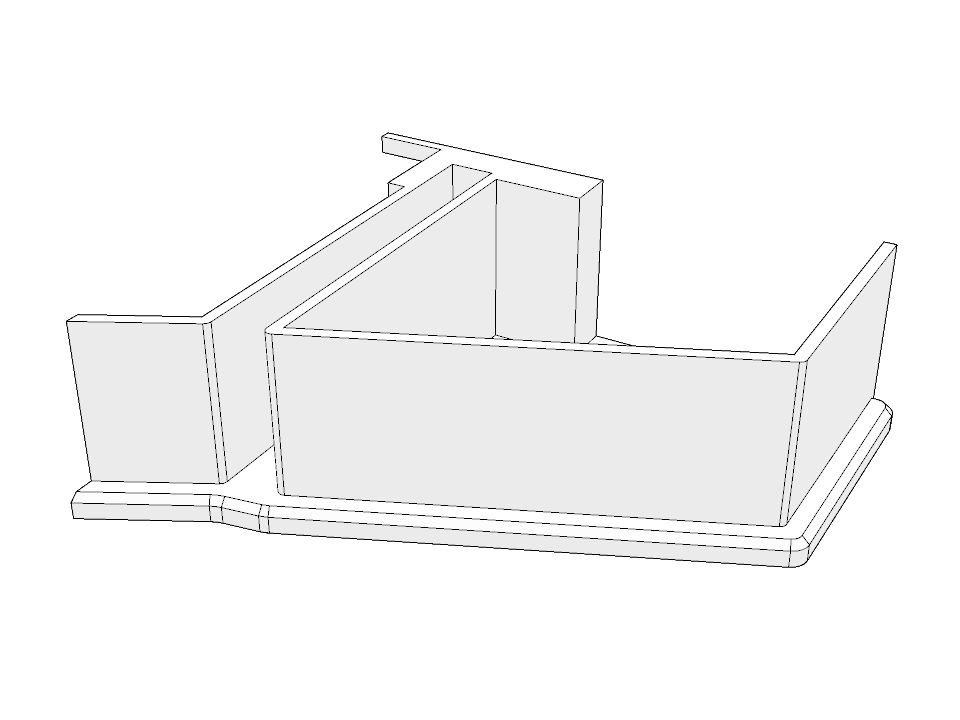
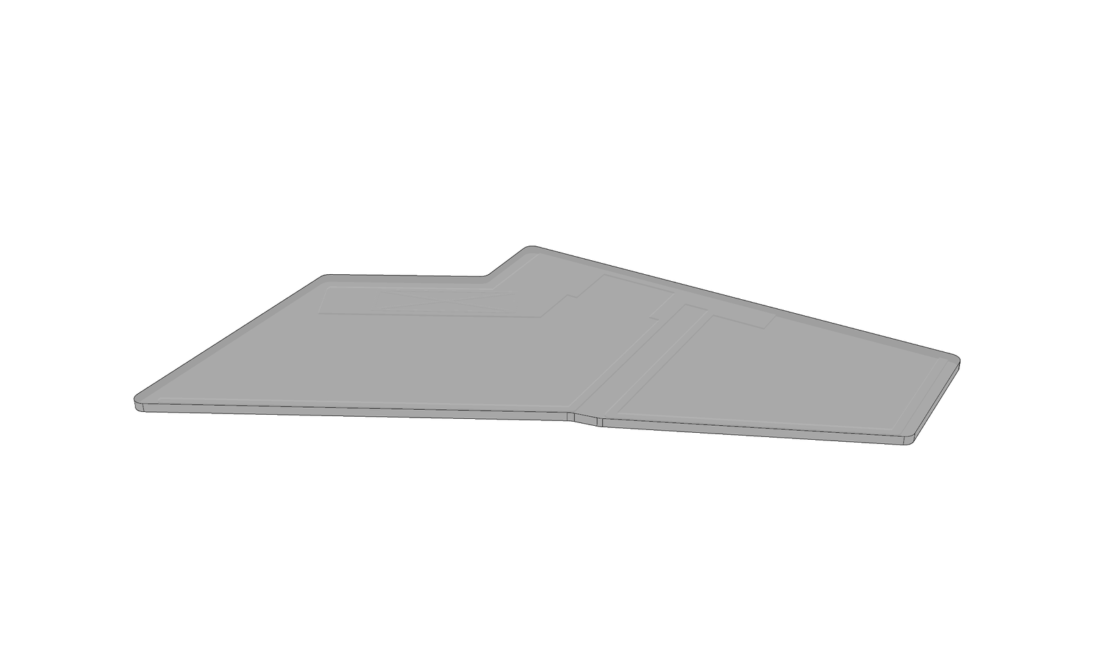
3D-Printed Floor Plan

The main floor plan is printed in PLA and in parts and then glued together to form two sections of the floor plan, the main floor plan is bigger and has magnets attached to it while the detachable section is smaller and is also attached with magnets to attach itself to the main one.

05


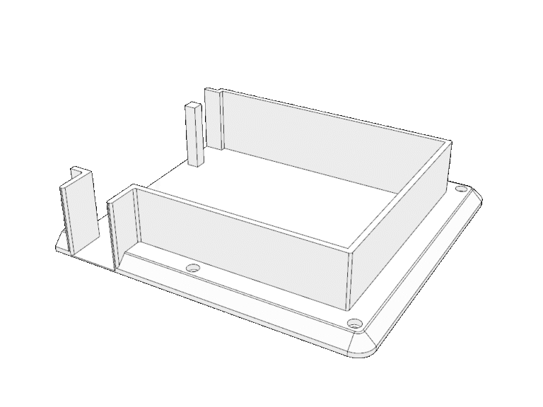
Detachable Wooden Panel

The detachable wooden panel aligns with the main floor panel’s perimeter, ensuring smooth linework and allowing bolted 3D-printed parts for flexibility.

Materials

3D Printed PLA

Stainless Steel Hardware

Wood Panel

Coated steel

Dimensions

811.12mm (Length)

438.64mm (Width)

78mm (Height)

Development Time

3 weeks 

Design Goal

The IHC floor plan reflects the design concept of The Peranakan Museum (TPM). Similar to TPM, its removable lighting plan panel enables users to reposition miniature objects on the floor plan, supporting flexible planning and curation of exhibition layouts for an interactive and adaptable design experience.

IHC Components Miniatures

01

Miniature Partitions

These miniature partitions are used to illustrate gallery sections or to assist in planning visitor circulation routes. They come in various sizes and feature chamfered corners, allowing them to be easily repositioned at 90-degree angles when necessary.

02

Mini Pedestals

These mini pedestals are scaled representations used to simulate the placement of display stands within the gallery space. Their compact form allows for flexible arrangement on the floor plan, supporting curatorial planning and spatial organisation.

03

Miniature Mannequins

These miniature mannequins feature a supporting column for distinction and are printed in the same color as other objects, unlike miniature humans with lower bodies, which are printed in grey for clear differentiation.

04

Miniature Figures

These mini figurines represent a diverse range of visitors, including male, female, children, and individuals using wheelchairs. Designed to scale, they are used to simulate human presence within the gallery space, helping curators assess sightlines, accessibility, and the overall visitor experience.

Materials

3D Printed PLA

Magnets

Dimensions

Various

Development Time

3 weeks 

Design Goal

These miniature objects, scaled at 1:500 to match the floor plan, are colour-coded for specific museums; in this case, purple. Each object contains embedded magnets, enabling secure attachment to the floor plan, which incorporates a coated steel bottom panel for stability and easy repositioning during exhibition layout planning.

Components List

1 x Part 01

1 x Part 02

1 x Part 03

1 x Part 04

1 x Part 05

1 x Part 06

10 x Part 07

Print Settings

Layer Height: 0.2

Wall Loops: 6

Top Layer: 6

Bottom Layer: 6

Advance Settings

Order of Walls:

Inner/Outer/Inner

Infill: 30%

Infill pattern: Gyriod

Temperature Settings

Nozzle: 200-210°

Bed: 50°

Total Print Time

20-30 Hours (Approximately)

Materials

PLA (Matte White)

1 x Acrylic Panel
(Detachable Section)

1 x Acrylic Panel
(Main Section)

1 x Acrylic Panel
(Main Section)

1 x Acrylic Panel
(Main Section)

1 x Coated Steel Panel (Detachable Section)

1 x Wooden Base Plate
(Main Section)

M4 Stainless Steel Bolts

24mm (x10) 

Stainless Steel Inserts

M4 x M8 X 12mm (x10)


M52 Magnets

M6 x 2mm (x30)

M8 x 2mm (x20)

Assembly

How to Prepare the Parts

This section outlines the process for inserting the stainless steel inserts into all the 3D printed parts necessary for the design assembly. It is important to complete this step before the assembly. Additionally, to ensure the stainless steel inserts remain securely embedded in the 3D printed parts, it is essential to use Maxi-Cure™ Extra Thick CA Glue for bonding plastics and metals.

How to Apply Maxi-Cure

Apply Maxi-Cure™ CA to one side of the parts to be joined, then press them firmly together for 10-20 seconds. For larger bonding surfaces, apply serpentine beads of the CA adhesive, ensuring sufficient spacing to allow for proper spreading. The adhesive will reach full strength within three hours. Clean the nozzle before securing the screw-on cap. To extend shelf life, refrigerate the product. Once cured, Maxi-Cure™ CA remains stable within a temperature range of -40°F to 220°F.

Steel Insert Feet

M4 x M8 x 12mm (x10)

IHC Assembly 01

01

Acrylic Panel (Main Section)

02

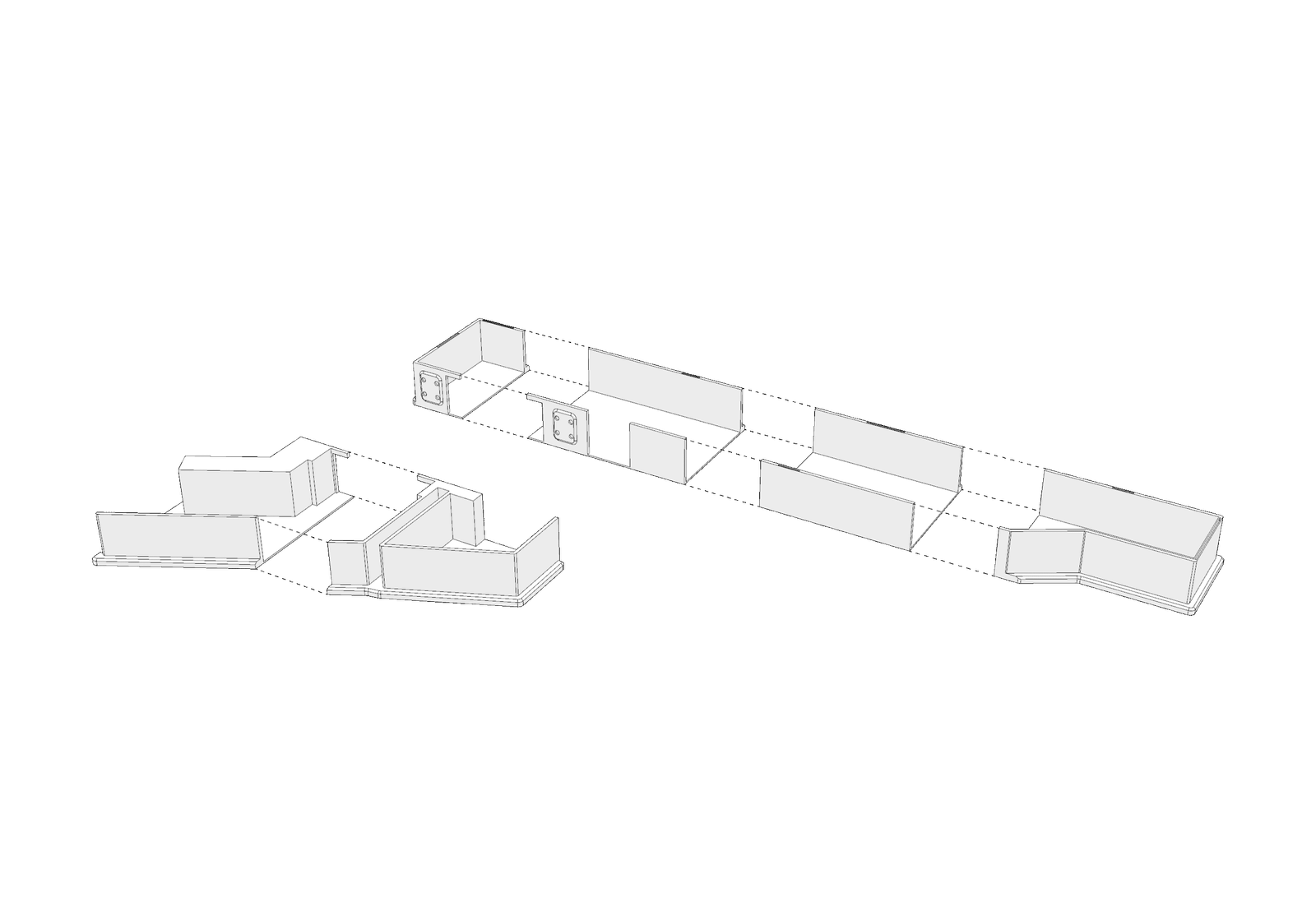
Glue Parts 01 + 02 + 03 + 04 together

03

24mm Bolt

04

Coated Metal Plate (Main Section)

05

Wooden Panel (Main Section)

06

Part 07

07

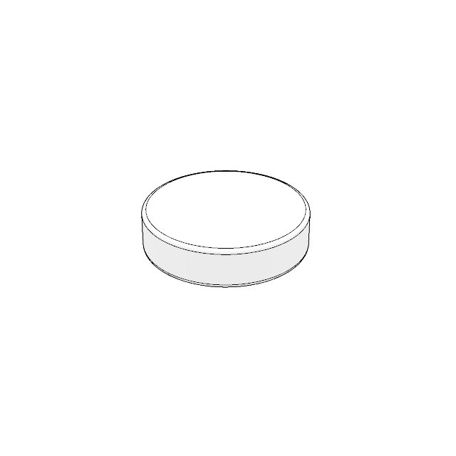
Affix 6mm x 2mm Magnets on the bottom of the 

IHC Assembly 02

01

Acrylic Panel (Detachable Section)

02

Glue Parts 05 + 06 together
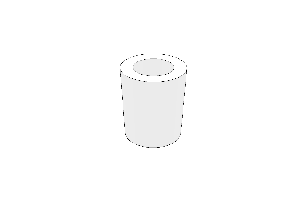
03

24mm Bolt

04

Coated Metal Plate (Detachable Section)

05

Wooden Panel (Detachable Section)

06

Part 07

IHC Components Miniatures

01

Mini Partitions

Affix 6mm x 2mm magnets to the underside of these miniatures.

02

Mini Pedestals

Affix 6mm x 2mm magnets to the underside of these miniatures.

03

Mini Figurines

Affix 8mm x 2mm magnets to the underside of these miniatures.

04

Mini Figurines

Affix 8mm x 2mm magnets to the underside of these miniatures.

01 || Miniature Partition 

L1000 x D150 x Full Height
L1500 x D150 x Full Height
L2000 x D150 x Full Height
L2500 x D150 x Full Height
L3000 x D150 x Full Height
L3500 x D150 x Full Height
L4000 x D150 x Full Height
(Scale 1: 500)

02 || Miniature Pedestals

L1500 x D1500 x H1800
L1500 x D1500 x H900
L1000 x D1000 x H900
L1500 x D500 x H900
L1000 x D500 x H900
L1500 x D500 x H2500
(Scale 1: 500)

03 || Miniature Mannequin

Male Mannequin
Female Mannequin
Child Mannequin
(Scale 1: 500)

04 || Miniature Figurines

Male Figurine
Female Figurine
Child Figurine
Wheel Chair Figurine
(Scale 1: 500)

Project Gallery

Project Timeline

Phase One

A 1:500 PLA scale model was produced to evaluate proportion accuracy and key elements, including walls, lighting tracks, and door widths. The model was reviewed by the production team to confirm alignment and details on scale and material selection.

Phase Two

After learning the client prefers PETG for its higher structural integrity over PLA, particularly given the 2.4mm thin walls, PLA was deemed inadequate. Therefore, all subsequent design iterations and parts will be produced using PETG to ensure durability.

Phase Three

With PETG confirmed as the final material, supporting hardware was adjusted accordingly. The steel plate was coated white to counter PETG’s translucency in thin sections, while a wooden board served as the base for securing hardware and the floor plan.