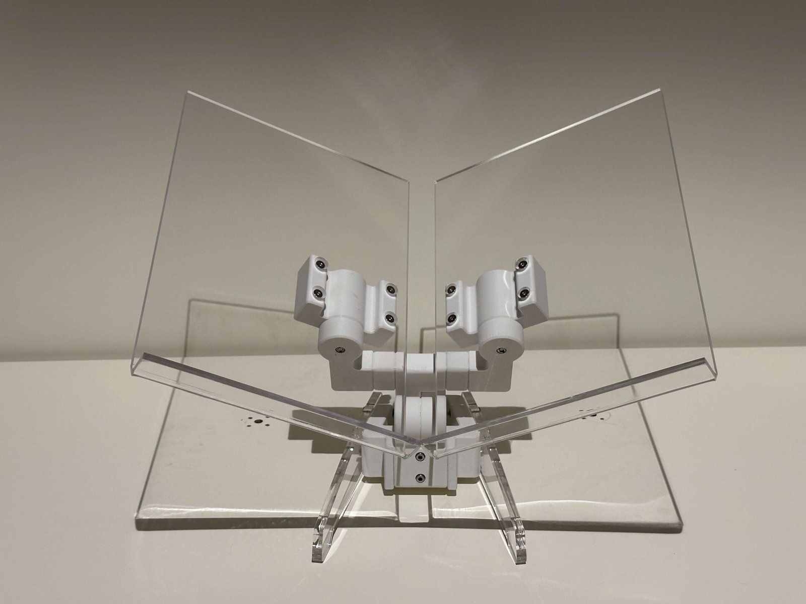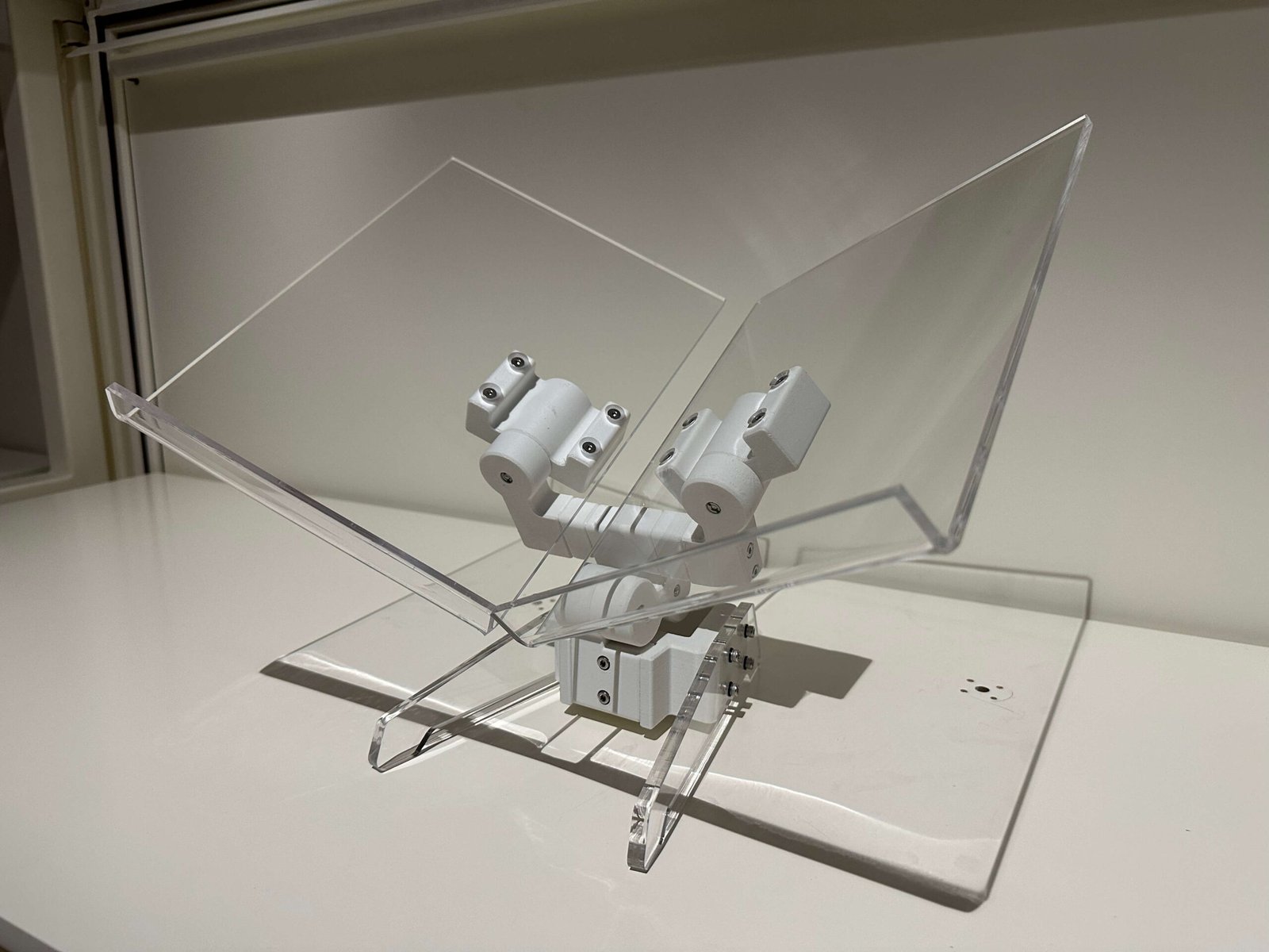

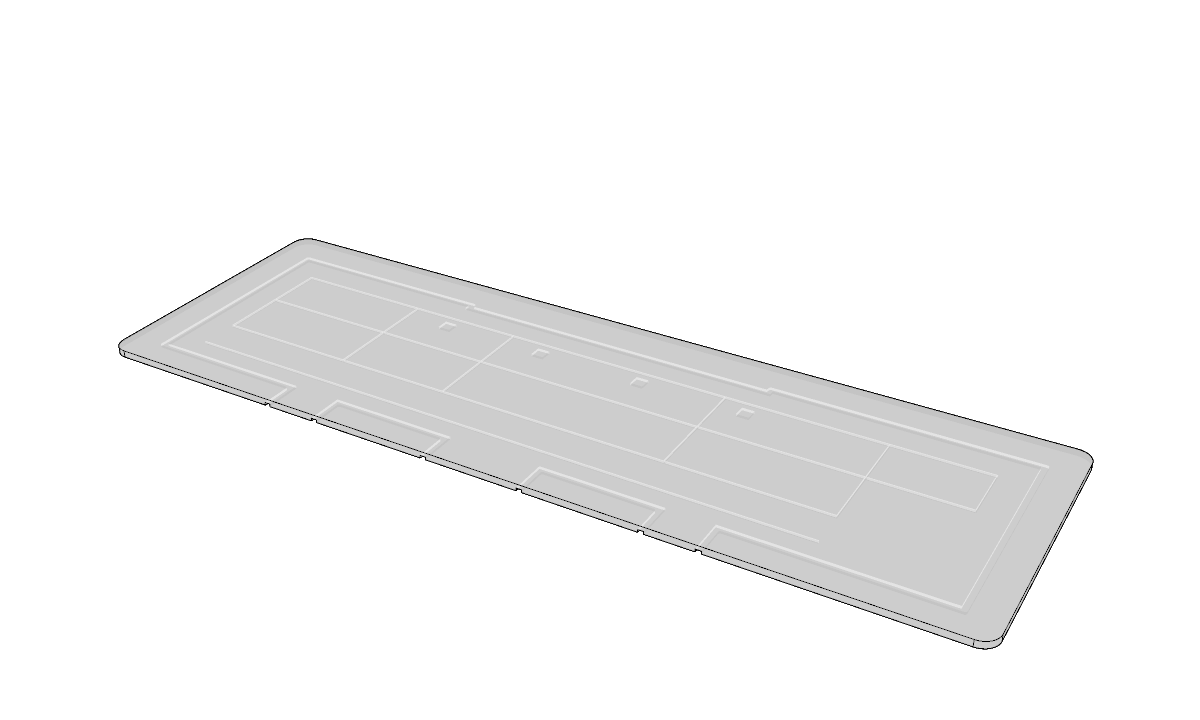
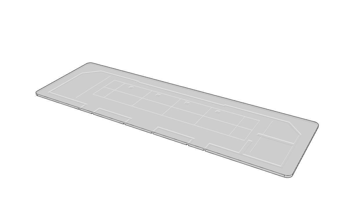
Detachable Acrylic Panel
This acrylic panel features the gallery’s lighting plan etched onto its surface. Its purpose is to help users visualise the placement of lighting within the gallery space, making it easier to plan and curate the exhibition effectively.
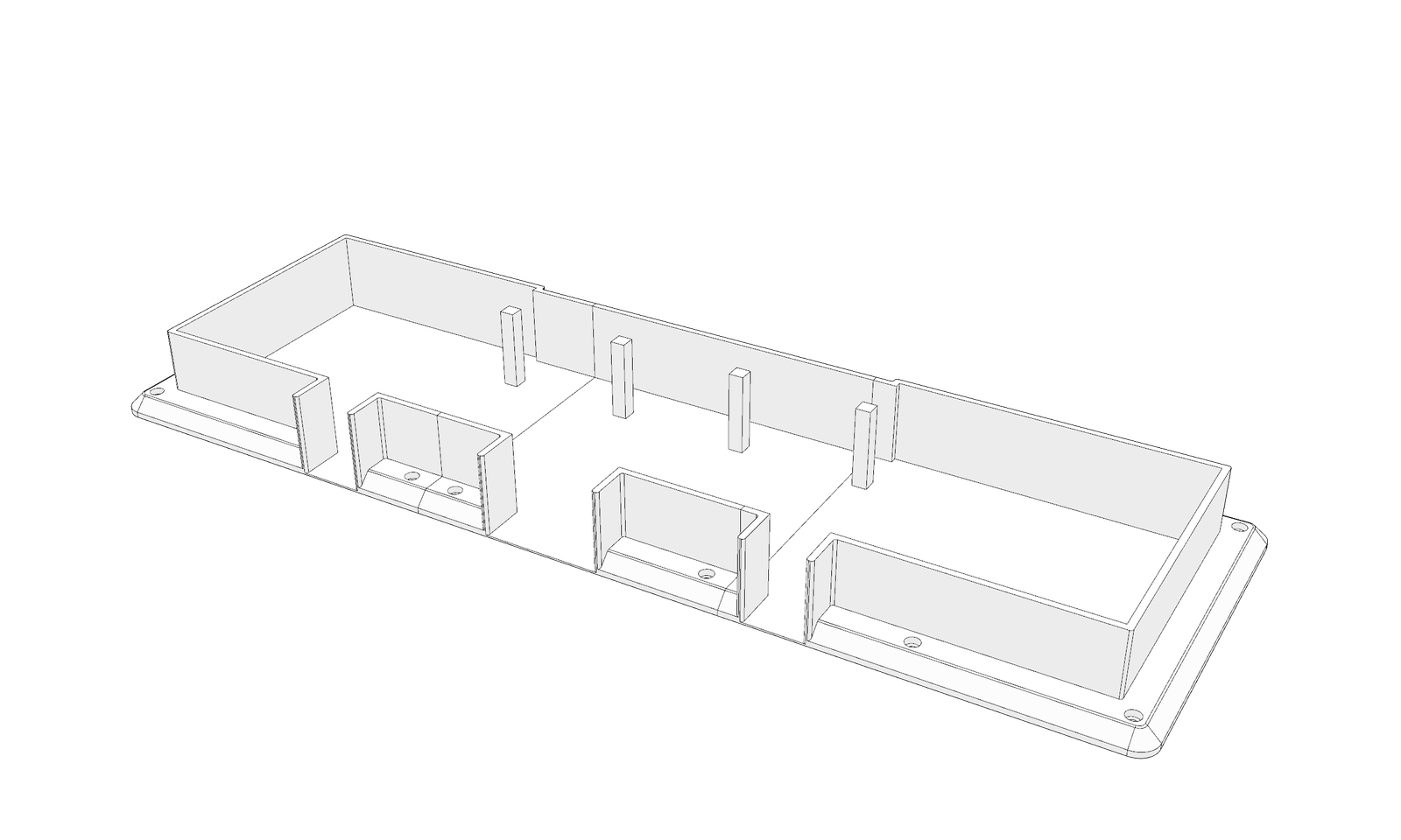
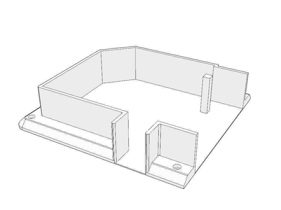
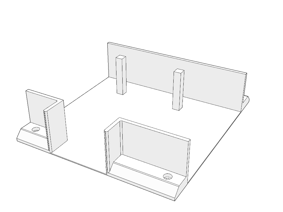
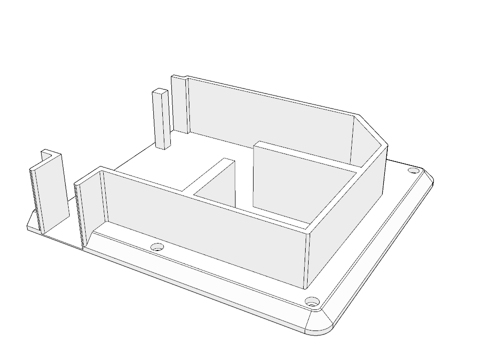
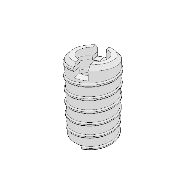
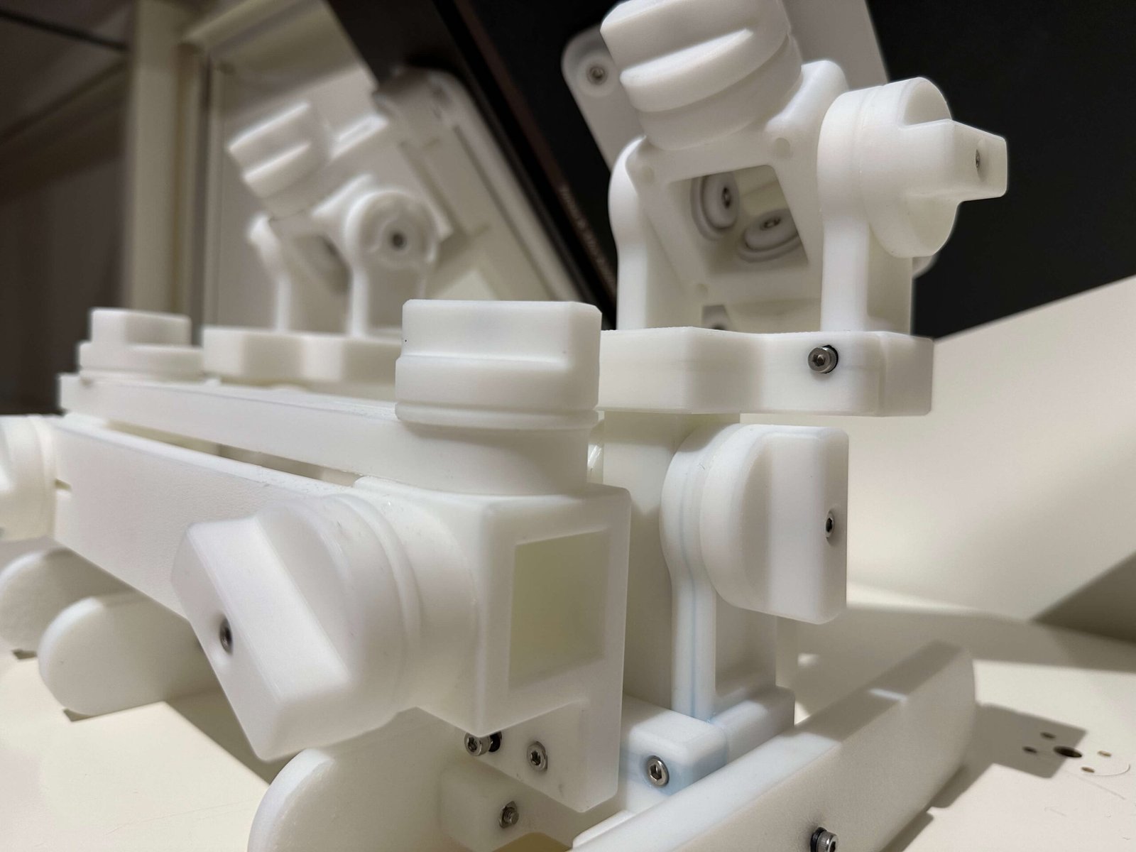
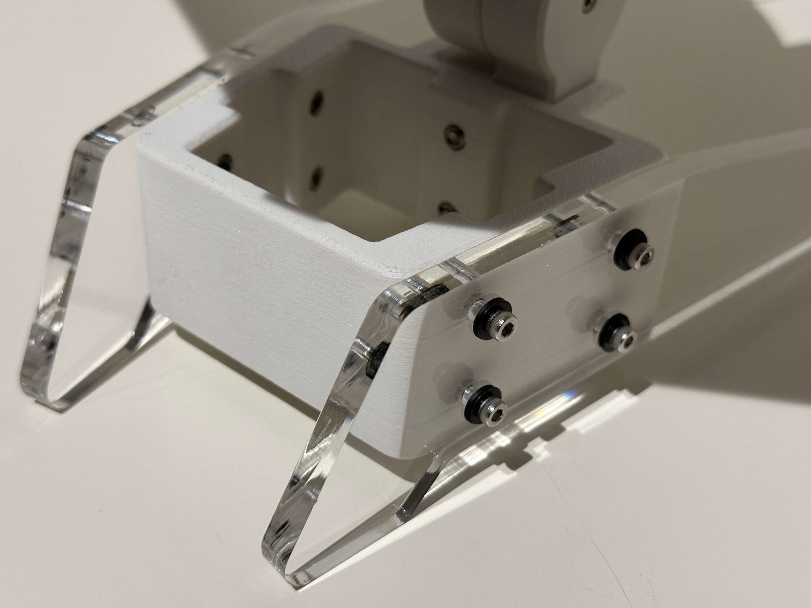
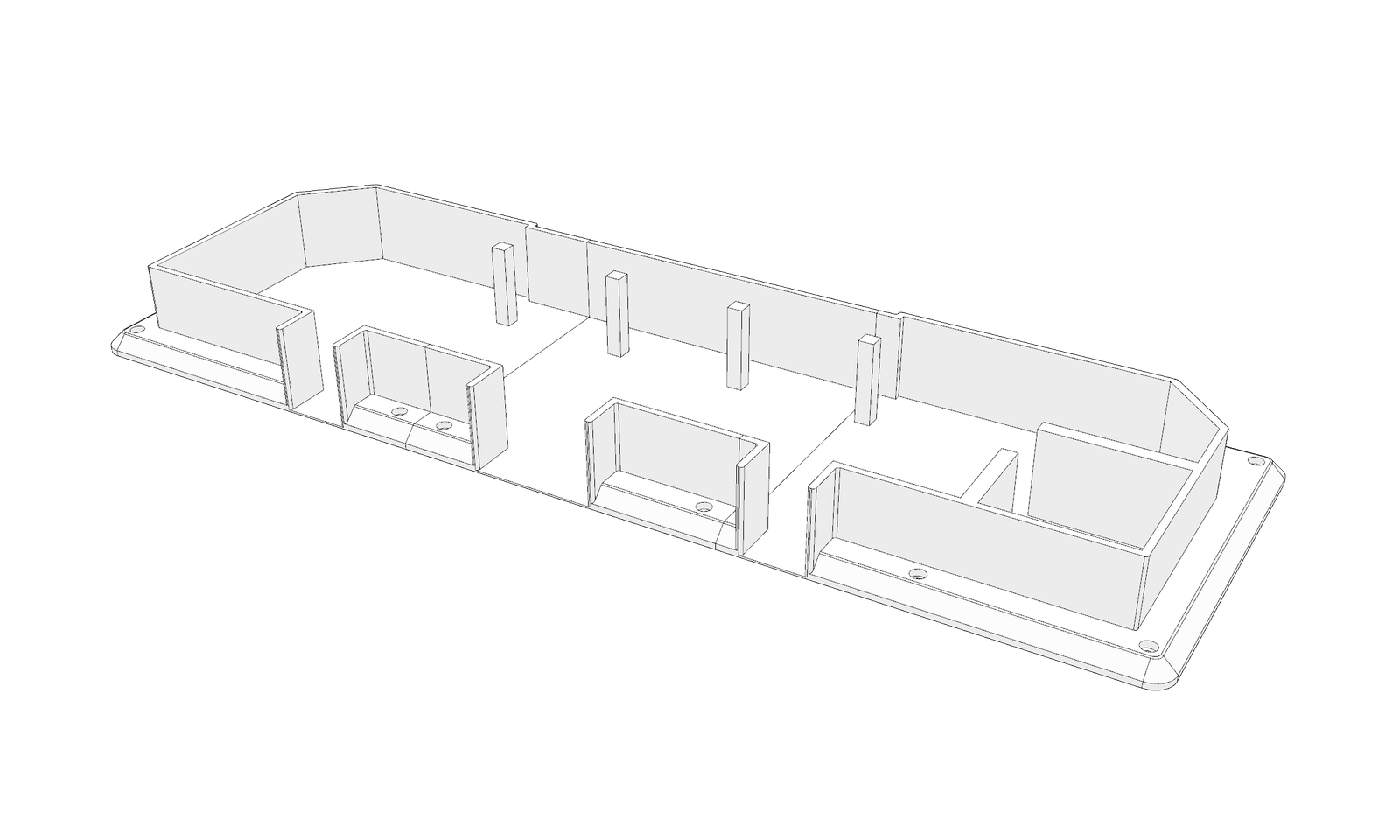
3D printed Floor Plan
This 3D printed floor plan design is modular and can be bolted and unbolted, allowing for updates in response to renovations or the incorporation of new, more permanent features within the gallery.
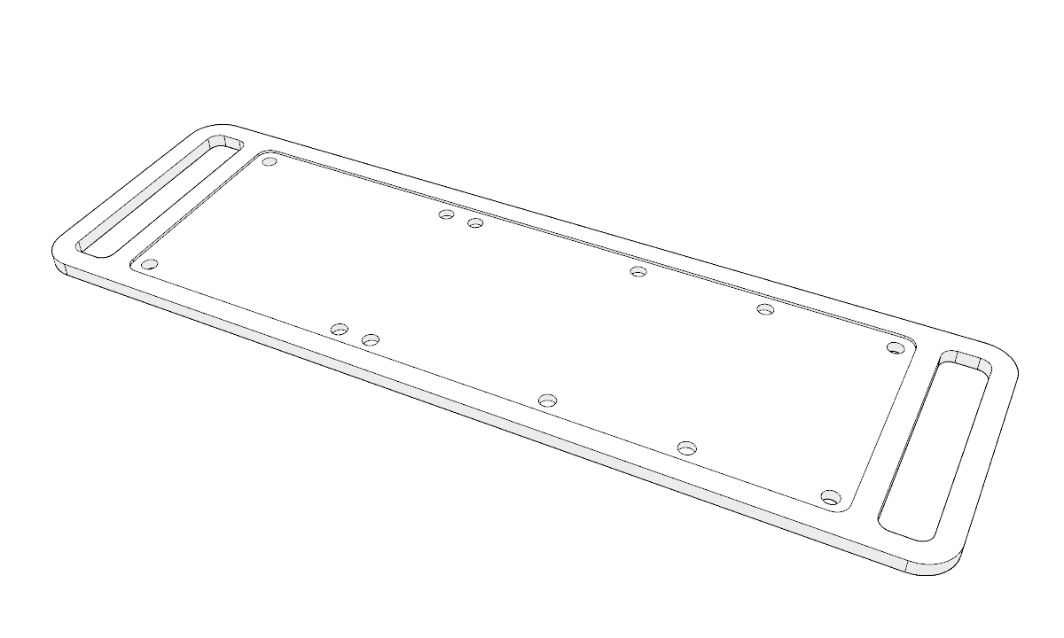
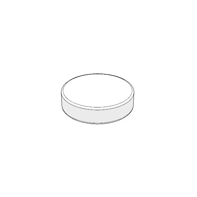
Wooden Panel
This wooden panel serves as the base of the entire floor plan structure. It provides foundational support, securing both the steel panel and the 3D-printed floor plan in place. Side handles are integrated into the panel design to facilitate easy transport.

Detachable Acrylic Panel
This acrylic panel features the gallery’s lighting plan etched onto its surface. Its purpose is to help users visualise the placement of lighting within the gallery space, making it easier to plan and curate the exhibition effectively.
3D printed Floor Plan
This 3D printed floor plan design is modular and can be bolted and unbolted, allowing for updates in response to renovations or the incorporation of new, more permanent features within the gallery.
Wooden Panel
This wooden panel serves as the base of the entire floor plan structure. It provides foundational support, securing both the steel panel and the 3D-printed floor plan in place. Side handles are integrated into the panel design to facilitate easy transport.


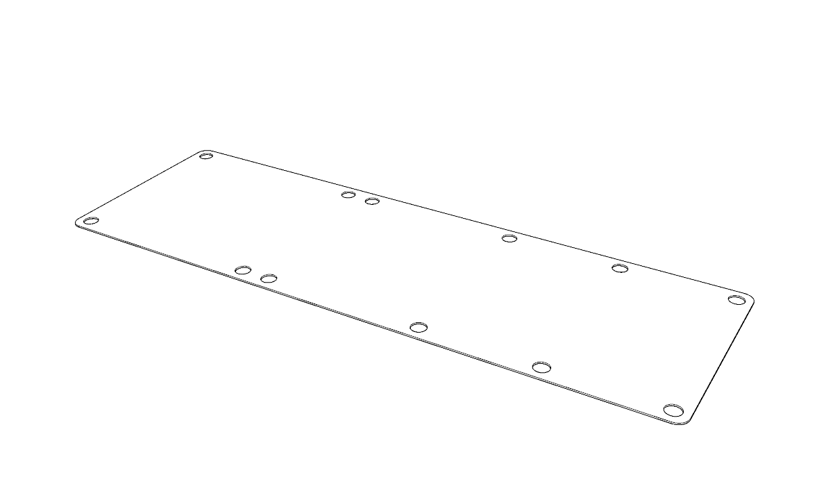 Place Steel panel onto the cut out of the wooden base
Once all four steel insert feet and eight steel insert holders have been securely glued in place, position the metal panel into the cutout section of the wooden base.
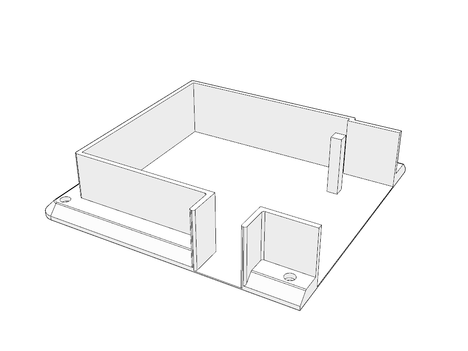
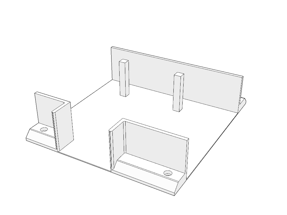
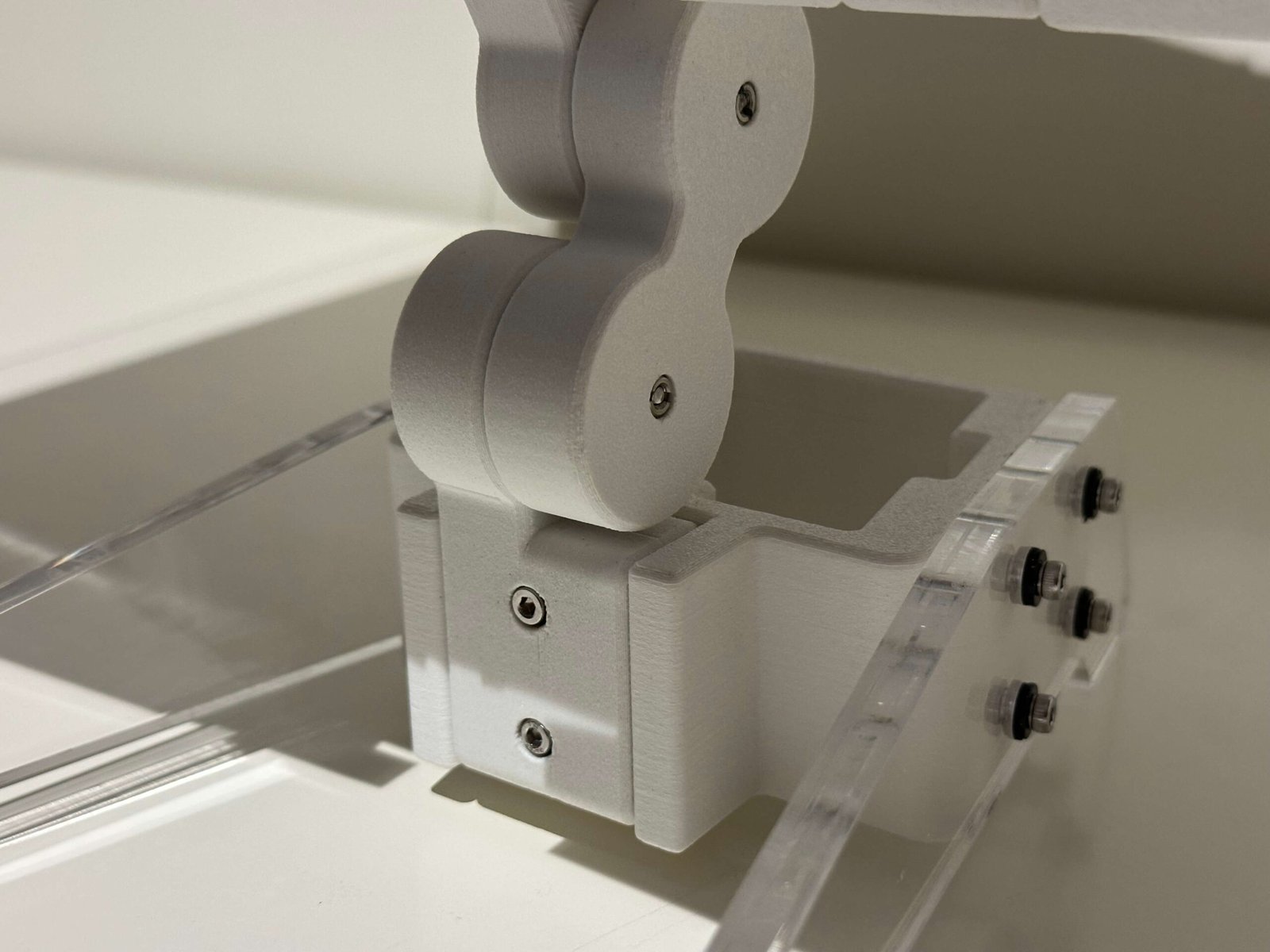
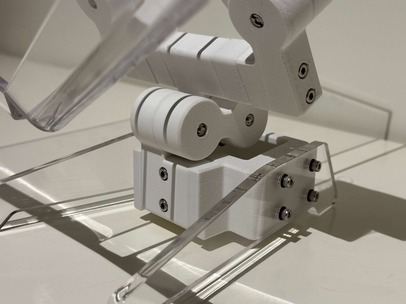
Glue the 3D printed parts as shown above and place it on the wooden base.
Before inserting the 3D-printed parts into the wooden base, ensure that all holes on the printed components are properly aligned with the corresponding features on the wooden base.
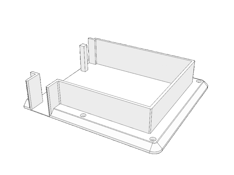
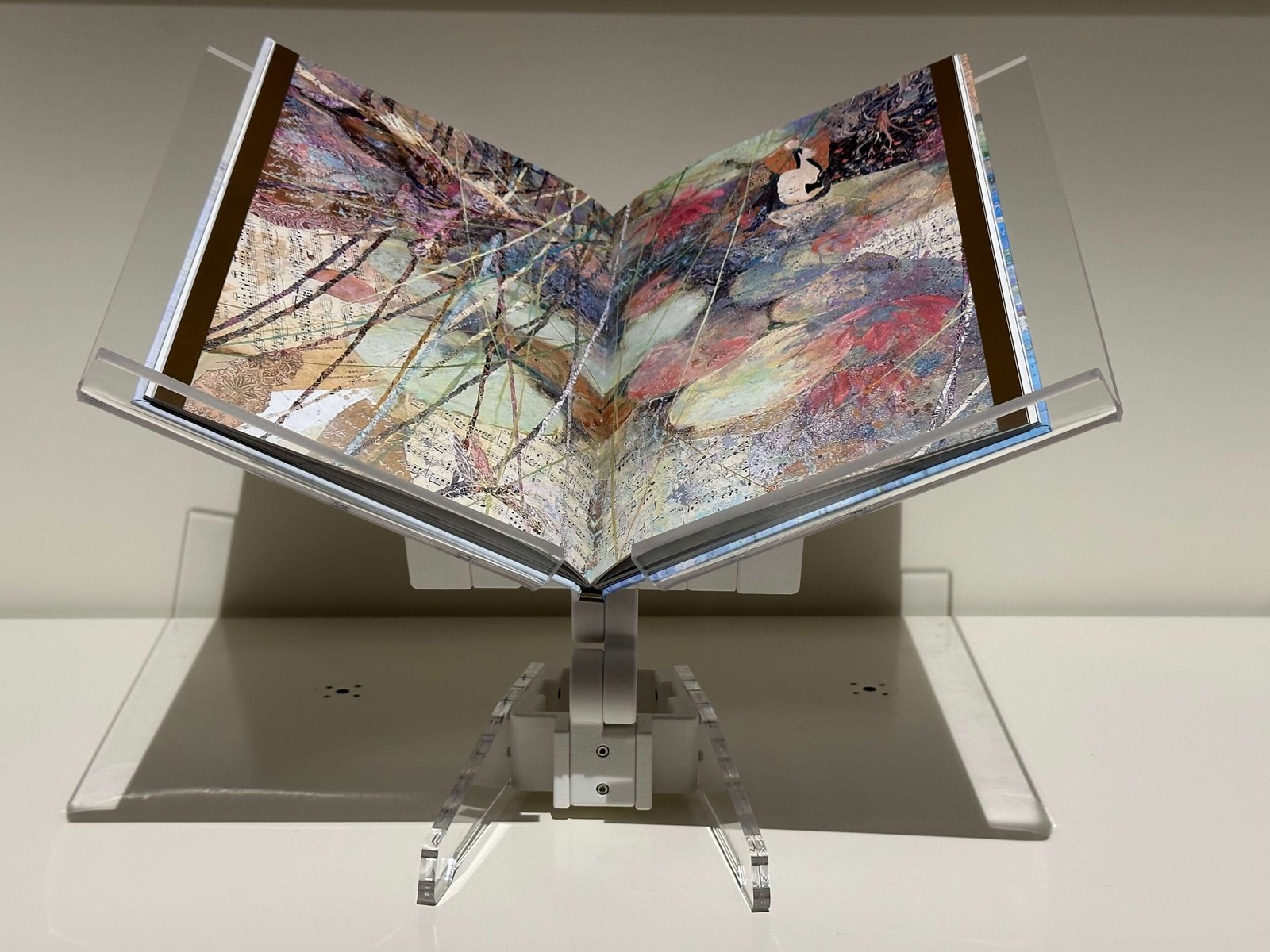
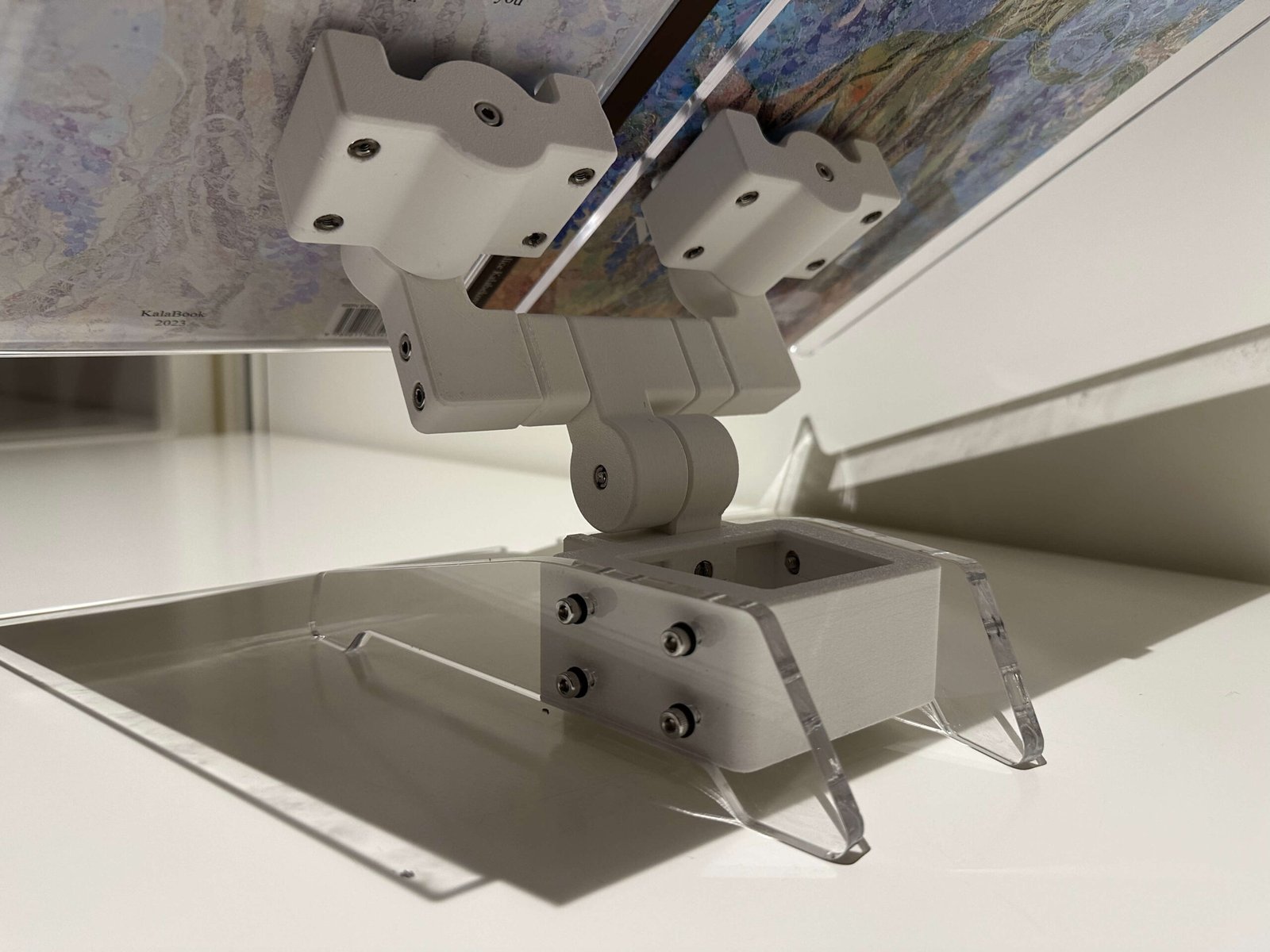
Place the Acrylic panel into the 3D printed perimeter of the floor plan
For this step, no gluing or hardware is required. Simply align the acrylic piece with the perimeter of the floor plan as shown.

Place Steel panel onto the cut out of the wooden base
Once all four steel insert feet and eight steel insert holders have been securely glued in place, position the metal panel into the cutout section of the wooden base.
Glue the 3D printed parts as shown above and place it on the wooden base.
Before inserting the 3D-printed parts into the wooden base, ensure that all holes on the printed components are properly aligned with the corresponding features on the wooden base.
Place the Acrylic panel into the 3D printed perimeter of the floor plan
For this step, no gluing or hardware is required. Simply align the acrylic piece with the perimeter of the floor plan as shown.

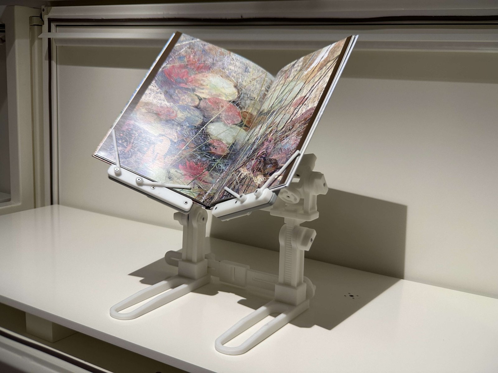
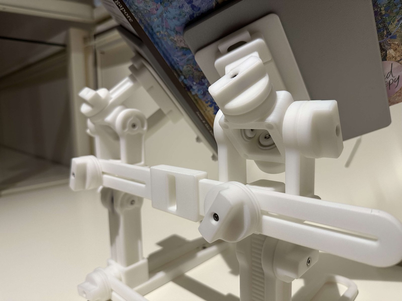
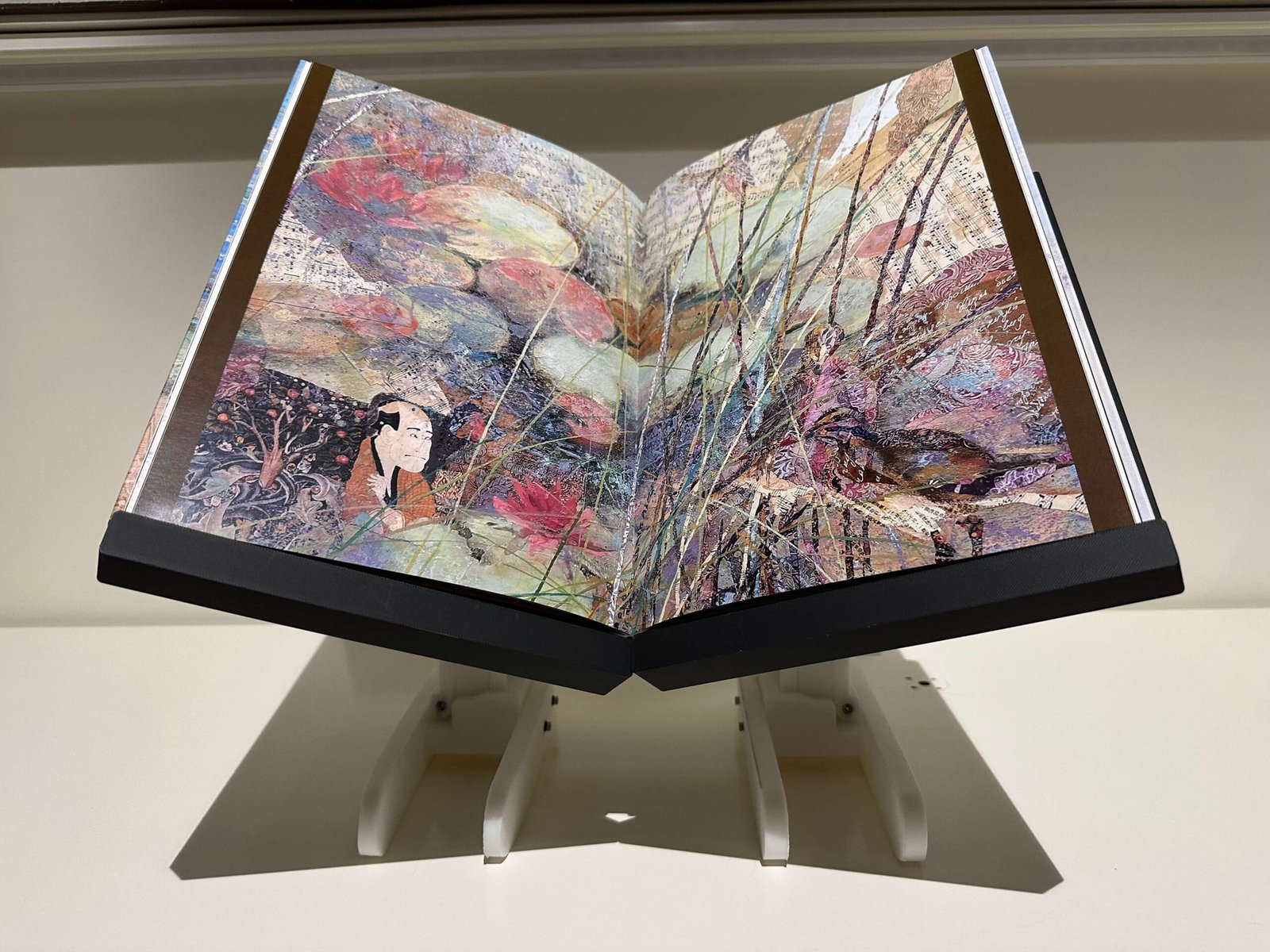
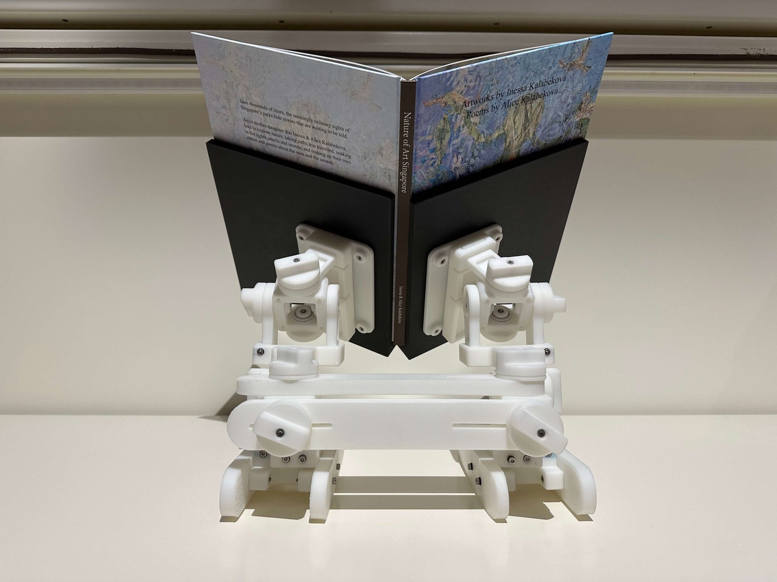
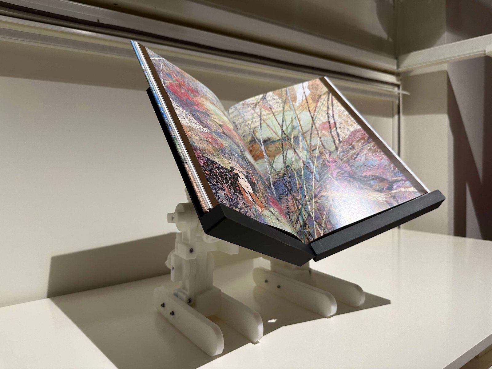
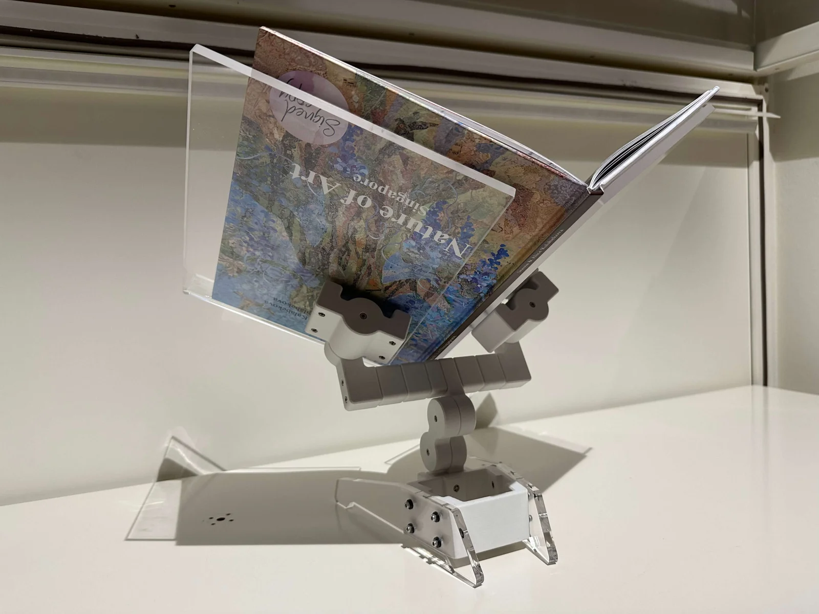
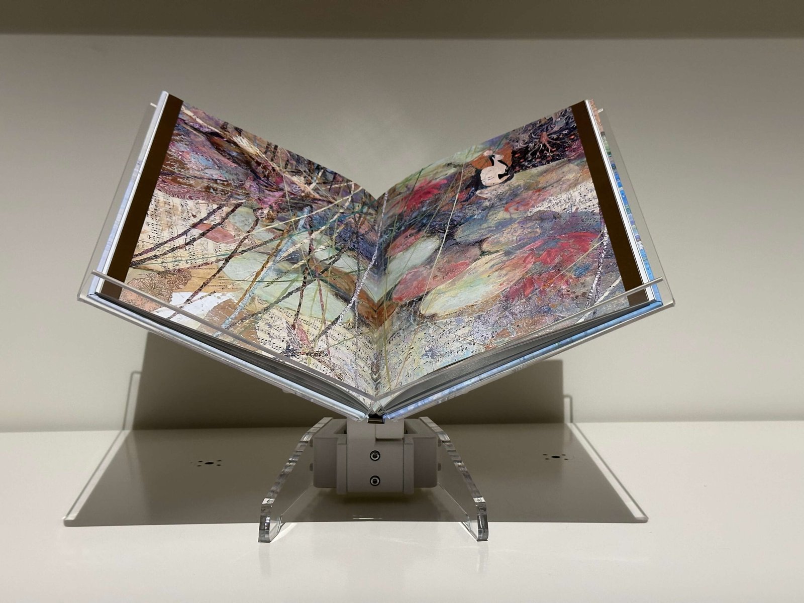
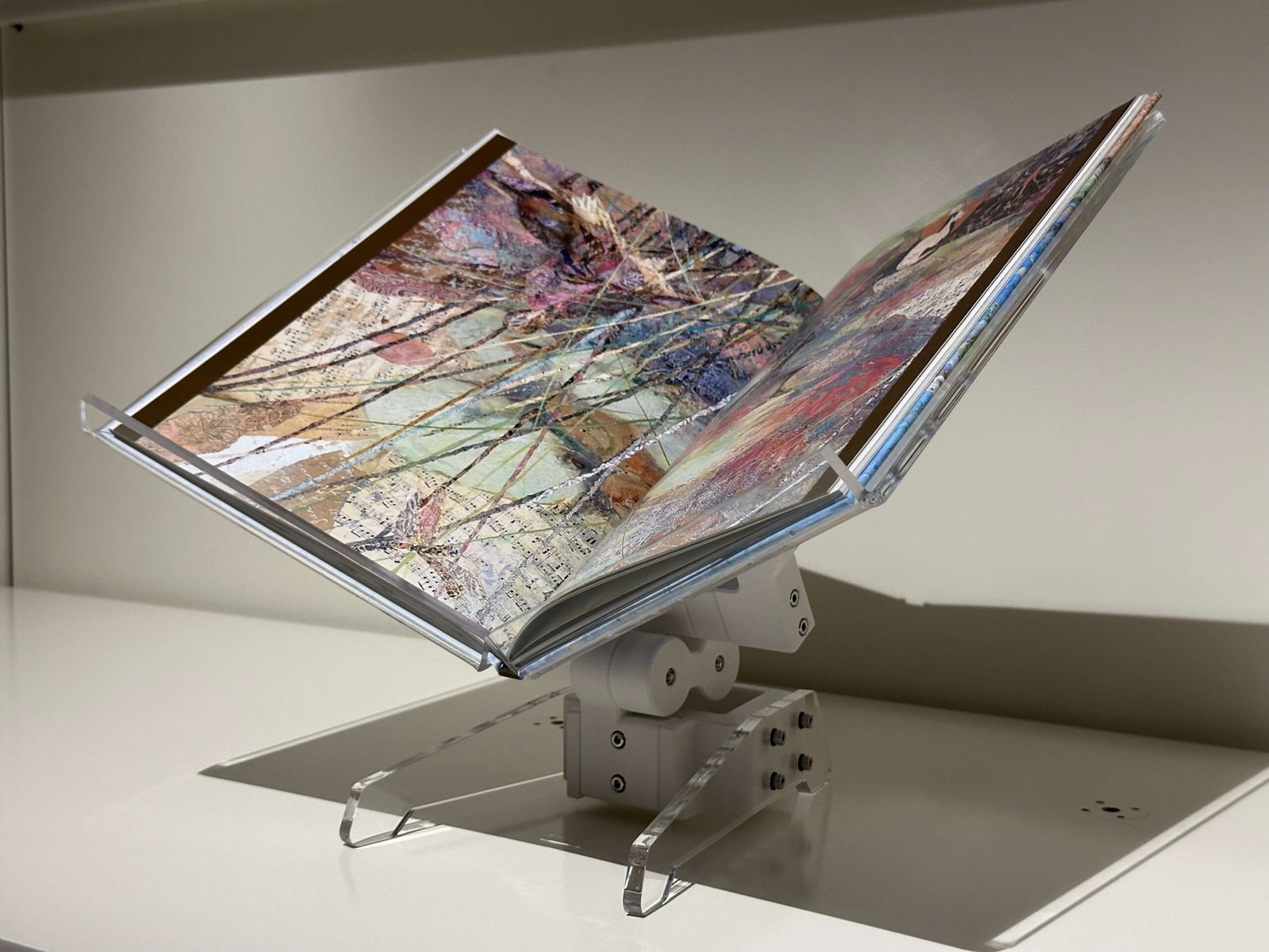
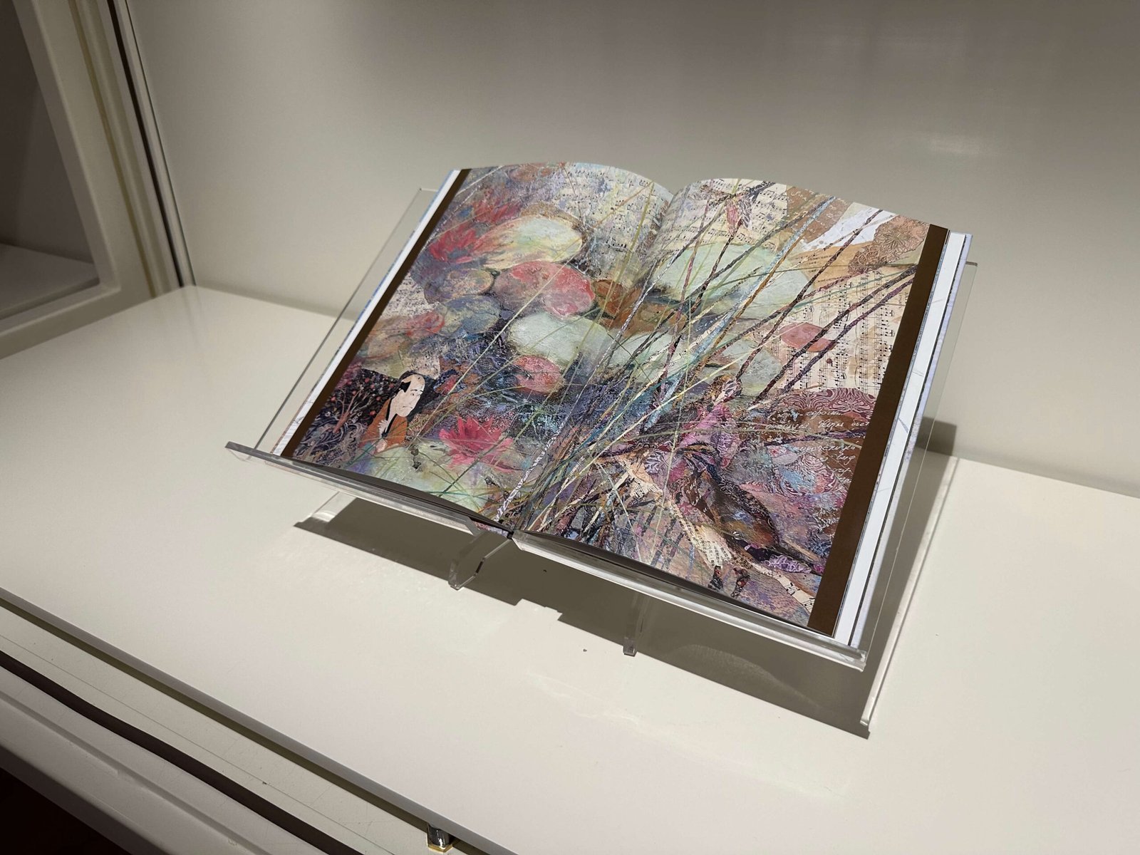
Completed Assembly (Iteration 02)